|
We use a combination of Free-Mo and Bend-track. Click here for more information about Bend-track
Module Specifications and Standards
1. Standard modules shall be 30 1/2 inches wide by any convenient length.
2. Fascia height is 6 inches with a 1 1/2 inch inside flange
3. Module height to top of the rail is 50 inches.
4. End plates are 1/2 inch birch plywood with integral T brace.
5. The module must provide two mainline tracks each spaced 10 inches from the centerline of the module.
6. Curved modules should be constructed with 1/4 inch bendable plywood, if available.
7. The top will be 2 inch thick extruded styrofoam however, a lamination of one-inch foam is permitted if it aids in lowering
the surface contours.
8. Modules will have integral, folding legs with ajustable levelers.
9. If the modeler wishes to build his or her own module they must utilize end panels purchased from the NBR&N group.
Track Specifications
Mainline Tracks
1. Minimum mainline rail size is code 83. All mainline rail must interface to code 83 at the joiner.
2. Standard (unmodified) HO gauge track is not permitted.
3. Except with prior group permission, there shall be no grades on mainline.
4. Roadbed shall be 1/4 inch thick. We recommend Vinylbed brand composite roadbed.
5. Roadbed conditions without ballast profile are acceptable.
6. Track and tie total height above roadbed must match Micro Engineering On30 code 83 flex track
7. Hand laid track is permissible.
8. Rails must end 1 inch from end of module.
9. The ties must run to the end of the module.
10. Stub turnouts are not permitted on the mainlines.
11. Uncoupling ramps are not permitted on the mainlines.
12. Turnouts must have positive throw (spring or equivalent) to maintain position.
13. Minimum center to center distance for parallel tracks is 3 inches on tangents and 3 3/8 on curves.
14. Minimum radius is 24 inches on mainlines.
Off Mainline Tracks
1. Both rails leading to off main tracks must have filled insulated gaps. The only exception to this is for simple stub ended
sidings.
2. Roadbed may vary according to conditions and need.
3. Stub turnouts are permitted.
4. Uncoupling ramps are permitted.
Recommended practices
1. While both switch machines and hand throws may used to actuate turnouts; the use of hand throws is encouraged where practical.
2. The use of standard ballast techniques is encouraged. A mix of (2) parts grey number 75 to one part cinder number 76 is
preferred. These are Woodland Scenics products and the fine grade should be used.
2. The occasional use of ground foam grass and soil in the ballast is recommended especially on less used trackage.
3. Rails may be painted rail brown with occasional rust streaks.
4. If telephone poles are used along the right of way, they must be placed on the inside of the module between the rail and
center.
Electrical and Power Standards
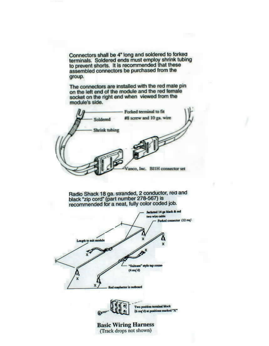
a. Mainline bus: 14 gauge stranded wire, red on outside rail, black on inside rail. Radio Shack 18 gauge stranded, 2 conductor,
red and black zip cord (part number 278-567) is recommended.
b. Each rail has a drop.
c. Terminal blocks used to make positive connections. One at each end of the module, for each track, and one in the center
of the module for each track. Forked connectors to be used, soldered to the wires, and connected to the terminal blocks.
d. Module to module connections shall be via two pin quick disconnects. Vanco, Inc. part number BL1H provides correct color
coding (red/black) and heavy wire gauge (10ga.) to withstand transportation abuse.
Connectors shall be 4 inches long and soldered to forked terminals. Soldered ends must employ shrink tubing to prevent shorts.
It is recommended that these assembled connectors be purchased from the group.
The connectors are installed with the red male pin on the left end of the module and the red female socket on the right end
when viewed from the side of the module.
Free-Mo
If a 30.5 inch standard module is larger than you would like to handle, consider building a Fremo module.
Concept:
Narrow modules (15 inches wide) used to simulate single track branch lines. Modules may be any length, straight
or curved.
Specifications:
1. Modules employ a single mainline track centered at each end.
2. Every module of more than 24 inches must have legs.
3. The modules are connected to each other with one clamp and held in alignment with pins.
4. Fascia height is 6 inches with a 1 1/2 inch inside flange.
5. Module height to top of the rail is 50 inches.
6. The top will be 2 inch thick extruded styrofoam however, a lamination of one-inch foam is permitted if it aids in lowering
the surface contours.
Click here for more information about Free-Mo
|